SOUNDBOOST: Effective RCA and Attack Detection for UAV via Acoustic Side-Channel
A review of SOUNDBOOST (DSN 2025), a post-hoc root cause analysis framework that uses a UAV's acoustic side-channel to attribute navigation failures to GPS spoofing or IMU biasing attacks.
SOUNDBOOST: Effective RCA and Attack Detection for UAV via Acoustic Side-Channel
Haoran Wang, Zheng Yang, Sangdon Park, Yibin Yang, Seulbae Kim, Willian Lunardi, Martin Andreoni, Taesoo Kim, Wenke Lee (Georgia Institute of Technology, POSTECH, Technology Innovation Institute)
DSN 2025 · Paper
What is this research about?
SOUNDBOOST is a paper that studies a root cause analysis (RCA) framework which determines, after the fact, whether an anomalous behavior of a drone (UAV) during flight was caused by an attack on the GPS or on the IMU.
Existing defenses assumed that the IMU is intact and detected only GPS attacks. As a result, when the IMU is also attacked, or when it is unknown which sensor has been compromised, the basis for judgment disappears. To solve this problem, the authors use the sound that is inevitably produced when the motors and propellers generate thrust, i.e., the acoustic side-channel, as a third reference independent of the sensors.
Sound is collected with a 4-channel microphone array mounted on the drone, and FFT is used to extract features in the blade passing (~200 Hz), mechanical (~2.5 kHz), and aerodynamic (~5.5 kHz) bands. A deep learning model (MobileNetV2), trained to fit these features to benign IMU values, predicts the drone’s 3-axis acceleration from sound alone. This prediction is compared with the IMU acceleration, and if the residual distribution deviates from normal (KS test), it is judged to be an IMU attack.
Next, the velocity obtained by integrating the predicted acceleration with a Kalman filter is compared with the GPS velocity to judge GPS spoofing; if the IMU was confirmed to be benign in the previous step, the IMU values are fused in as well.
In an evaluation on a real PX4-based vehicle, IMU biasing attacks synthesized in firmware were detected 100% of the time. Real GPS spoofing performed with HackRF was detected 79% of the time using sound alone and 89% when the benign IMU was also used, outperforming existing techniques, and the system also proved robust against attacks that interfere with the sound using a speaker or another drone.
What security threat does this paper respond to?
It responds to sensor spoofing attacks targeting UAV navigation sensors, and to situations where it is unknown which sensor the attack targeted.
Navigation sensors: core sensor modules that measure data so that an aerial vehicle (UAV) can determine its own position, velocity, attitude (tilt), and heading.
- Position and velocity measurement: GPS / GNSS (receives satellite signals to measure current latitude, longitude, and altitude)
- Attitude and orientation measurement: IMU (Inertial Measurement Unit: measures tilt and rotation rate using accelerometers and gyroscopes)
- Compass role: magnetometer (measures azimuth/heading)
- Precise altitude measurement: barometer / ultrasonic, laser altimeter
- GPS Spoofing: Civilian GPS signals have no authentication. So injecting fake satellite signals makes the drone misperceive its own position. The 2011 incident in which Iran landed and captured an RQ-170 is a representative example.
- IMU Biasing Attack: Systematic errors are injected into the accelerometer or gyroscope with out-of-band signals such as ultrasound above 20 kHz (e.g., Rocking Drone). The controller makes incorrect corrections, and the drone flies abnormally.
The real problem lies not so much in the attacks themselves as in the premise of existing defenses. Techniques such as SAVIOR and Control Invariant (LTI) detect GPS attacks on the assumption that “the IMU can be trusted.” Since it has already been shown that the IMU can also be attacked, there is no means of determining whether the GPS or the IMU is the cause (possibly both) when an anomalous flight occurs.
What this paper wants to say
Cross-validating sensors against each other creates a circular problem of “which one to trust.” By reconstructing the actual motion from a third physical reference that is hard for an attacker to manipulate, namely the sound produced by the motors and propellers, the root cause (RCA) of a sensor attack can be identified.
Key claims:
- The acoustic side-channel is a physical byproduct of thrust generation, so it cannot be eliminated, and it strongly correlates with acceleration.
- Using the acceleration predicted from this signal as the reference, IMU attacks and GPS attacks can be identified separately.
- SOUNDBOOST is not a real-time defense but a post-incident (post-hoc) forensic RCA tool. It operates after a mission failure is observed.
Threat Model
- Assumptions (trusted)
- The UAV hardware and firmware are benign.
- Navigation relies only on GPS and IMU (LiDAR and vision are optional, so they are excluded).
- The UAV operates in low-sensitivity failsafe mode, attempting an emergency landing on sensor failure.
- Attacker capabilities
- Fully knows the current flight status, such as the flight path and position.
- Performs spoofing or biasing on the GPS or IMU from the ground. The distance is limited by the flight altitude.
- The attack can happen at any time after takeoff is complete and before landing begins.
- The goal is not to crash the drone but to stealthily manipulate its position and path.
- Attacks on the acoustic sensor (the detector itself)
- Even record-and-replay attacks using a commercial portable speaker (up to about 100 dB) are considered.
- Attacks that cancel or inject phase-aligned sound using directional speakers or large loudspeakers are costly and impractical, so they are excluded from the scope. However, §IV-D also evaluates such attacks through simulation.
Core research content - step-by-step flow
Step 0 Background: control loop and attack surface
It is a loop that goes Sensors (GPS/IMU) → state estimation (KF fuses the accuracy of GPS with the high rate of IMU) → Control Algorithm → PID → Actuator (motor/propeller) → motion → back to sensor measurement.
GPS is accurate but has a slow update rate, while the IMU is fast but accumulates drift (a cumulative error phenomenon in which small sensor errors keep adding up over time, so the computed position or attitude increasingly diverges from the actual state). So the two are fused with a KF, and this very dependency structure becomes the attack surface.
Step 1 Basis for the acoustic side-channel
Three types of noise are produced when thrust is generated.
| Noise | Band | Cause |
|---|---|---|
| Blade passing | ~200 Hz | number of blades × rotation speed |
| Mechanical | ~2.5 kHz | electromagnetic vibration of motor/ESC |
| Aerodynamic | ~5.5 kHz | blade–air interaction (turbulence, vortices) |
- During ascent, all four motors speed up, so the sound becomes louder and higher. During turns, the speeds of diagonal motor pairs differ.
- By mounting the 4-channel microphone array off-center from the airframe and using TDoA, each propeller can be distinguished. The fact that a closer microphone hears the sound louder is also used for this distinction.
- Challenges stated in the paper: there is no dataset pairing UAV sound with IMU data, and there are environmental variables such as wind.
Step 2 Overall architecture
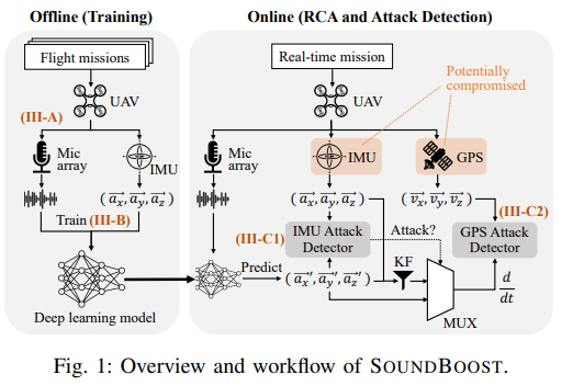
- Offline: The DL model is trained with flight sound and the benign IMU’s (ax, ay, az).
- Online/Post-hoc: Sound → model → (ax′, ay′, az′) is obtained. With these values, ① the IMU Attack Detector and ② the GPS Attack Detector (via the KF) are run. Here, the KF input is selected by a MUX according to the IMU verdict.
Step 3 Acoustic Signature Generation
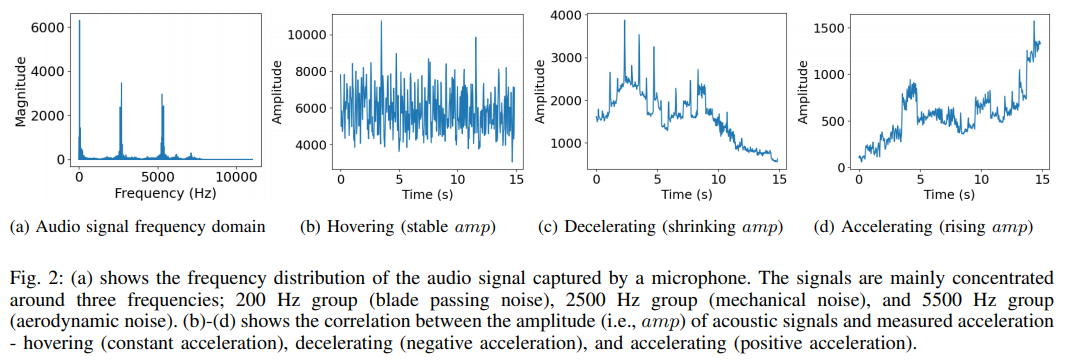
- FFT is performed per time window to convert to the frequency domain.
- Fig. 2a: Energy is concentrated in three groups: 200 Hz, 2.5 kHz, and 5.5 kHz.
- Bands above 6 kHz are removed. This serves to keep only the characteristic bands, but it also has the security effect of preventing ultrasonic IMU attack signals above 20 kHz from affecting the microphone path.
- Fig. 2b–d: The amplitude of the aerodynamic band stays constant during hovering, decreases during deceleration, and increases during acceleration. This is the direct basis for being able to map sound to acceleration.
Step 4 Sensory Mapping - learning sound → acceleration
- Model: ResNet101, MobileNetV2, and Neural ODE were compared, and MobileNetV2 was finally adopted.
- Alignment and loss: Sound and IMU are aligned with a sliding window, and the model is trained with MSE using the IMU as ground truth. This also has the side effect of mitigating IMU measurement noise.
- Time window: It must be larger than the IMU sampling period, and long enough to capture the whole acceleration process yet short enough not to miss rapid maneuvers. 0.5 seconds was chosen through experiments (0.1–2 s).
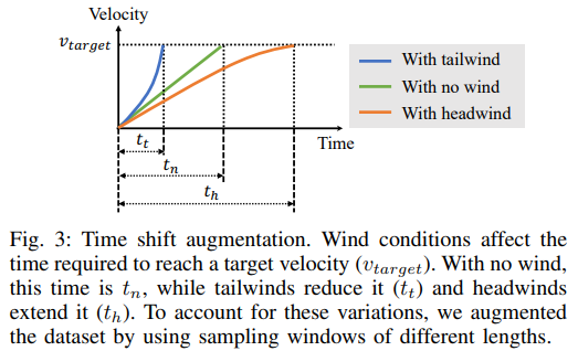
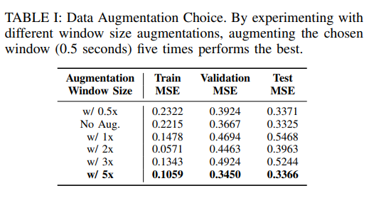
- Data Augmentation (Time Shift, Fig. 3): With a tailwind, the target velocity is reached quickly (tt), and with a headwind, it is reached slowly (th). That is, tt < tn < th. Small windows simulate tailwinds, and large windows simulate headwinds. Since the tailwind segment already fits within the base window, augmentation focused on large windows.
Step 5 RCA ① - IMU attack detection
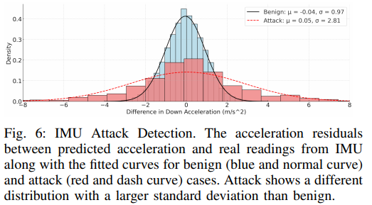
- For each window (0.5 s), the residual = IMU acceleration − acoustically predicted acceleration is computed.
- In benign flight, this residual is close to a normal distribution.
- It is compared with the benign distribution using the Kolmogorov–Smirnov test, and if it deviates significantly, it is judged to be an IMU attack (OOD detection).
- This verdict directly determines whether to trust the IMU in the next step.
Step 6 RCA ② - GPS attack detection
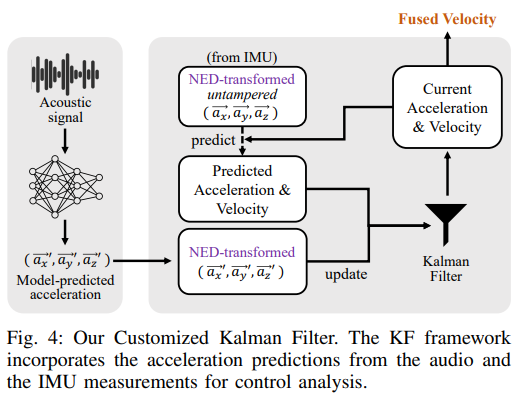
First, the acceleration transformed into NED coordinates is fed into the KF to estimate velocity (v₁ = v₀ + a·t).
| Version | Condition | Predict step | Update step |
|---|---|---|---|
| V1: Audio-only KF | IMU compromised | acoustically predicted acceleration | acoustically predicted acceleration |
| V2: Audio+IMU KF (Fig. 4) | IMU benign | IMU acceleration | acoustically predicted acceleration |
In V2, the weights of the two sources are dynamically adjusted based on covariance.
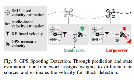
Detection (Fig. 5): The error between the fused velocity and the GPS velocity is accumulated and its running mean is tracked. If this value exceeds the maximum running mean of benign flights (after removing outliers), it is judged to be GPS spoofing.
→ As a result, it does not stop at “an anomaly occurred” but attributes it all the way to whether it was caused by the IMU or by the GPS.
Step 7 Implementation
PX4 + Holybro X500, a Raspberry Pi companion computer, MAVSDK/MAVLink, and a ReSpeaker 4-mic USB array were used. RCA is completed on board without a Jetson or the cloud, and the signature generation overhead averages about 2.4%.
Step 8 Evaluation
(a) Efficacy of the acoustic side-channel (§IV-A) — Table I, Fig. 6 (blue distribution)
- 36 benign training flights (6 scenarios: hovering, ascent, descent, forward flight, turns) and 21 test flights (10 IMU attacks, 11 GPS attacks) were all conducted outdoors.
- Table I: Augmenting the 0.5 s window by 5x performed best (Test MSE 0.3366, Val 0.3450). The authors state that they intentionally overfit slightly to respect physical constraints.
- Feature importance: Removing the aerodynamic band increases the MSE 3.77x, revealing it as the key feature. The blade passing and mechanical bands have an effect of less than 0.12x, and background noise less than 0.05x.
(b) IMU attack detection (§IV-B) — Fig. 6
- The attacks were synthesized in firmware: 5 gyroscope Side-Swing (positive bias injection) and 5 accelerometer DoS (random noise), each lasting 10 seconds during hovering. Together with 10 benign flights, 20 flights in total.
- The z-axis residual distribution spread widely compared to benign (σ = 2.81, red curve in Fig. 6).
- TPR 100%, with an average detection delay of 2.3 seconds. The one FP is explained by unstable flight due to low battery.
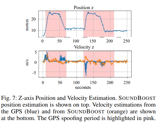
(c) GPS attack detection (§IV-C) - Table II, Fig. 7
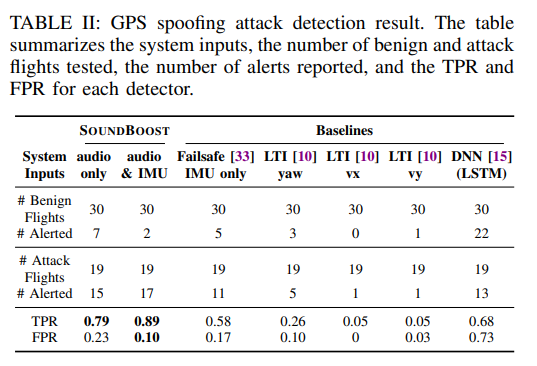
- Real attacks were performed with GPS-SDR-SIM + HackRF One. Cases of spoofing to a location 10 m away during hovering and of spoofing to a point on the mission path were covered, with 30 benign periods and 19 attack periods (60–90 s each).
| Method | TPR | FPR |
|---|---|---|
| SOUNDBOOST audio-only | 0.79 | 0.23 |
| SOUNDBOOST audio+IMU | 0.89 | 0.10 |
| Failsafe IMU-only (ArduPilot style) | 0.58 | 0.17 |
| LTI yaw / vx / vy | 0.26 / 0.05 / 0.05 | 0.10 / 0 / 0.03 |
| DNN (LSTM) | 0.68 | 0.73 |
- Fig. 7: During the spoofing period while hovering (pink), the GPS velocity and the SOUNDBOOST-estimated velocity diverge significantly.
- The average detection time is about 18.1 seconds after the attack starts.
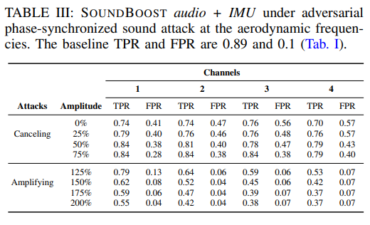
(d) Robustness to acoustic spoofing (§IV-D) - Table III
- Real attacks: A drone of the same model was flown at a distance of 0.5–2 m, and a max-volume replay attack with a speaker was also performed, but there was no effect. The cause is the lack of phase alignment and attenuation with distance. At 0.5 m away, only 46% of the original intensity remains.
- Simulation (Table III): An attacker with perfect control over phase was assumed.
- Amplifying the aerodynamic band by 2x drops the TPR from 0.89 to 0.37 (4 channels). This is the most effective bypass.
- Full cancellation keeps the TPR relatively high at 0.70 but raises the FPR. Detection only becomes oversensitive; bypassing it is hard.
- When limited to the physically feasible range (54–146%), performance stays roughly between the audio-only level and the IMU-only level.
Step 9 Discussion
- Concurrent GPS and IMU attacks: The authors argue that attacking both at once while keeping the drone from crashing is practically difficult. Even if it happens, GPS can be judged with audio-only after the IMU verdict.
- Generalization: It handles unseen trajectories and maps, but retraining is required when the airframe model changes.
- Extensions: Actuator DoS can be detected because the acoustically predicted acceleration approaches zero. On the other hand, attacks that take over all actuators cannot be detected. In multi-IMU environments, thresholds must be learned separately per model.
How does this research differ from existing methods?
- It does not assume a trusted sensor. SAVIOR and Control Invariant (LTI) detect GPS attacks on the premise that the IMU is benign. SOUNDBOOST treats both GPS and IMU as subjects of verification and uses a physical signal outside the sensors, sound, as the reference.
- It is post-hoc forensics, not a real-time defense. The goal is not immediate intervention. It is to identify the cause after a mission fails and to decide which sensor to trust in subsequent state estimation.
What did I learn from this paper?
① Methodology: design the verification channel to be physically separated from the attack channel.
SOUNDBOOST cuts off everything above 6 kHz. This is preprocessing to keep only the characteristic bands, but it is also a design that prevents ultrasonic IMU attack signals above 20 kHz from entering the verification path. Even though the attack and the defense share the same physical medium (sound), the two channels are separated by frequency band. The principle of “using a physical byproduct that cannot be eliminated as the reference, and making sure that reference does not overlap with the attack medium” is a framework that can be applied directly when designing other CPS detectors.
② Threat model: include the detector itself as an attack target, and bound the attacker’s capabilities with physical constraints.
This paper does not stop at claiming that “sound is hard to manipulate.” It puts spoofing of the acoustic sensor directly into the threat model and evaluates it at three levels.
- Realistic attacks: replay attacks using another drone or a portable speaker
- Worst case: a simulation assuming an attacker with perfect control over phase
- Physically feasible range: limited to 54–146%, based on the measurement that signal intensity drops to 46% at 0.5 m
It is an approach that draws the boundary of “what the attacker can do” not arbitrarily but with measured physical quantities. It shows how the threat model of a defense paper gains credibility. From the standpoint of doing attack research, I also learned that, conversely, finding an attack that can cross this boundary (phase synchronization, distance attenuation) becomes a counterexample to this paper.